
Inside Our Workshop: How We Build Our Loudspeakers
A loudspeaker takes shape long before its first listening session. It starts with a drawing, a sheet of MDF and a series of decisions about how the cabinet, drivers and crossover will work together. In our workshop, machining, assembly and measurement are connected parts of the same process.
1. Precision begins with the cabinet
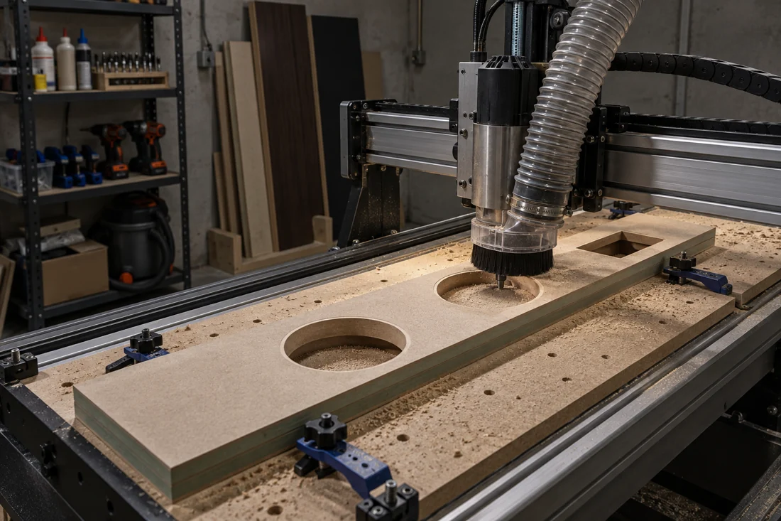
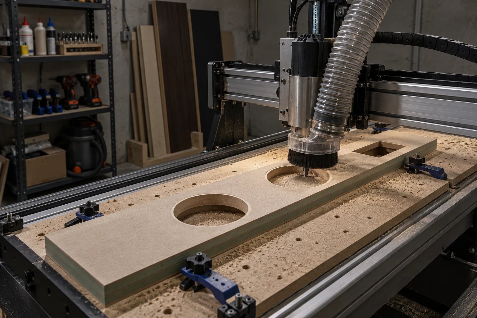
We use three-axis CNC machining to cut MDF panels, driver openings and the parts that form the cabinet interior. Repeatability matters: a small change in a recess, joint or internal partition can affect how the next stage comes together.
The machine provides the geometry. Assembly turns those separate pieces into a cabinet. We bring the panels together, check their alignment and clamp the joints while the adhesive cures. Driver seats, mating edges and internal passages all deserve attention before the enclosure is closed.
MDF gives us a consistent material to machine and assemble. But the material alone does not make a good enclosure. Panel dimensions, joints, internal partitions and damping all contribute to how the cabinet behaves.
2. The space inside has a job to do
Inside our transmission-line cabinets, partitions create a folded acoustic passage. This allows a longer path to fit within a cabinet that remains practical for a listening room.
A woofer radiates sound from the back of its cone as well as the front. The transmission line loads that rear radiation. Around its intended operating range, output from the line opening can contribute to the low-frequency response. The result depends on the driver, passage length and cross-section, damping and the position of the opening.
The lining visible inside our cabinets is part of that tuning. Absorbent material helps control unwanted internal sound, particularly higher-frequency energy that we do not want emerging from the line. Its amount and placement matter: simply adding more is not automatically better.
We treat the enclosure and driver as one acoustic system. The folded passage is a design choice to develop and test, rather than a shortcut to guaranteed bass performance.
3. HPL: the surface we live with
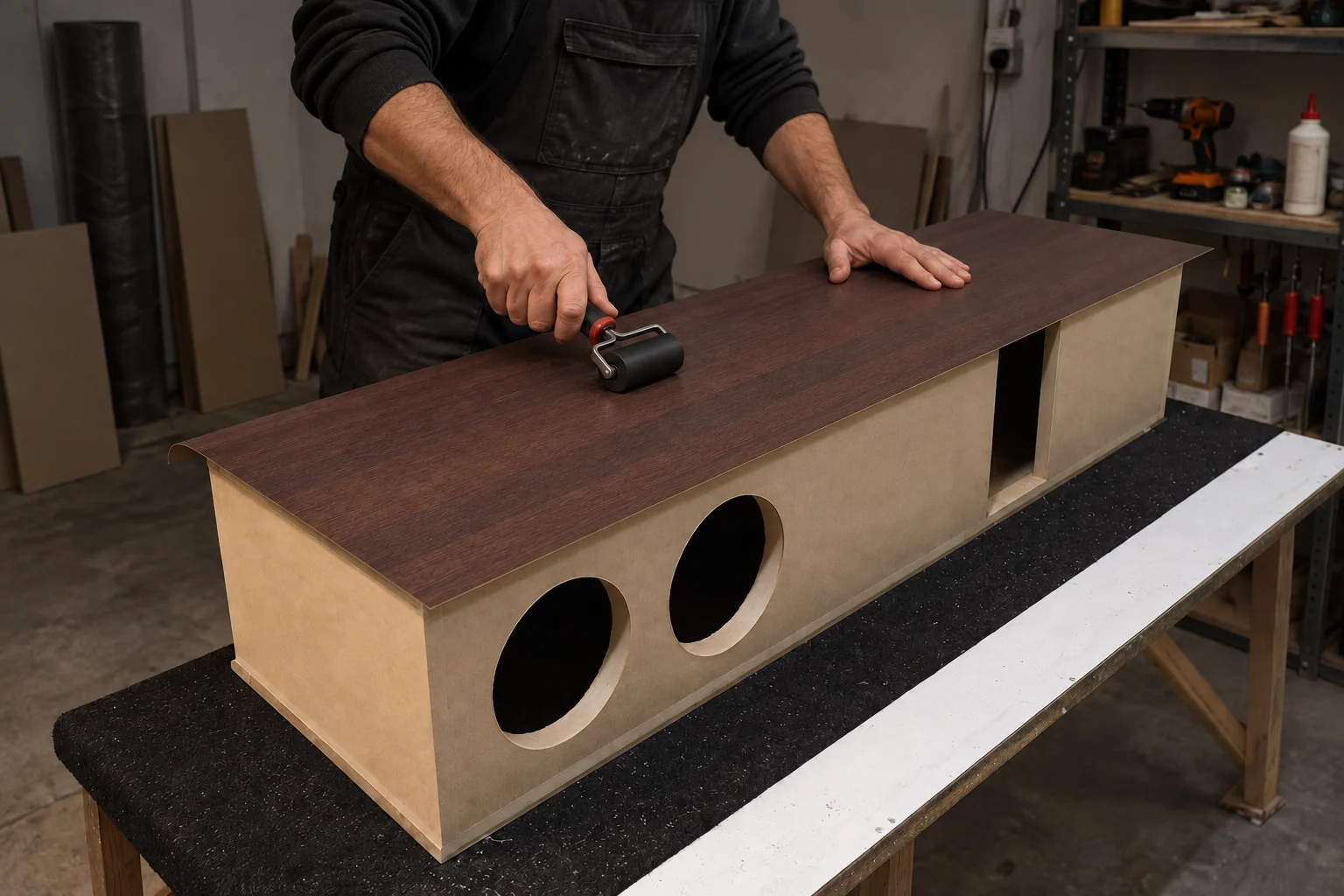
We finish our cabinets with high-pressure laminate, or HPL. It gives us a choice of textures and woodgrain appearances with a durable surface suited to everyday indoor use.
The panel is prepared, the laminate is bonded to it and pressure is applied as part of the bonding process. We allow the sheet to extend beyond the panel edges before trimming it flush. That small allowance helps achieve full coverage and a clean finished edge.
The attraction is practical as well as visual. HPL offers resistance to everyday wear, light scratches and incidental moisture. It is not indestructible, and a laminate surface does not make an MDF cabinet waterproof. Careful bonding, finished edges and sensible care remain important. We recommend wiping with a soft, lightly damp cloth and drying the surface, keeping standing water away from seams.
4. From a digital model to a part we can hold
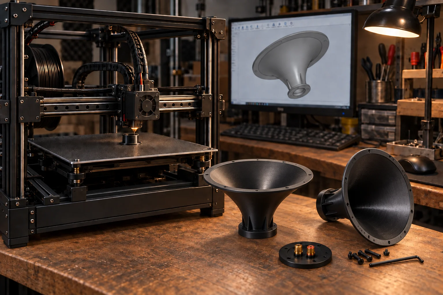
Some parts are made specifically for our designs. We model and 3D-print horn bodies for the high-frequency drivers, internal inserts and mounting plates for the rear terminals.
The printed horn is the acoustic shape in front of the driver; it is not the complete high-frequency transducer. Likewise, a printed terminal plate holds the electrical connectors rather than replacing them.
Working from a digital model lets us adjust a contour, mounting point or fit and produce another version for evaluation. A horn profile influences how sound spreads, so its shape deserves more than a visual check. Printing turns the design into a physical part that can be fitted, inspected and assessed as part of the loudspeaker.
5. The crossover brings the drivers together
A passive crossover divides the signal between the drivers and shapes their overlap. Its purpose is to make their different working ranges combine into a coherent whole.
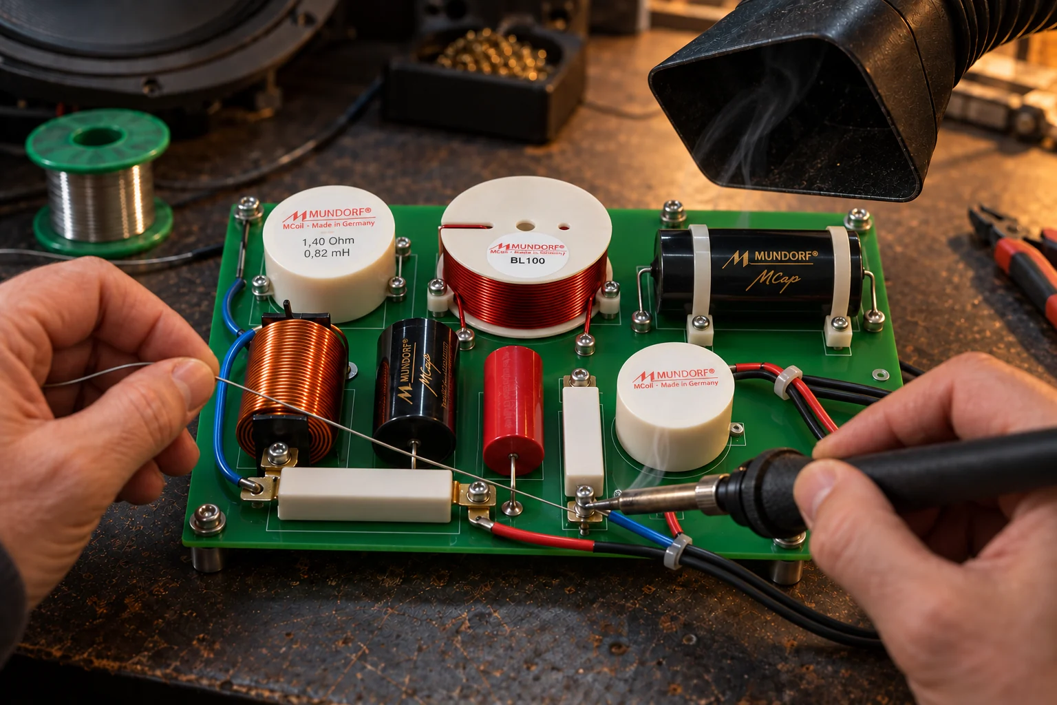
Our component selection includes Mundorf and Monacor parts, alongside other specialist suppliers where the design calls for them. Inductance, capacitance, resistance, tolerance and power handling matter more than a label on its own. Film capacitors and bipolar electrolytic capacitors are different component types, selected according to the requirements of the circuit.
We use second- and third-order electrical filter sections where they suit the drivers and the intended integration. Their ideal asymptotic slopes are 12 and 18 dB per octave respectively. A steeper section can reduce unwanted overlap and attenuate frequencies outside a driver’s intended range, but it also changes phase behaviour and the way the drivers combine.
The acoustic result is not determined by electrical order alone. Each driver’s own response, impedance and position on the baffle also contribute. That is why a textbook calculation is a starting point, followed by simulation, prototype changes and measurement.
Assembly matters too. Components need secure mounting, dependable solder joints and sensible wire routing. The spacing and orientation of inductors deserve care because nearby coils can interact magnetically. A well-considered circuit needs an equally considered physical layout.
6. Measure, adjust, listen
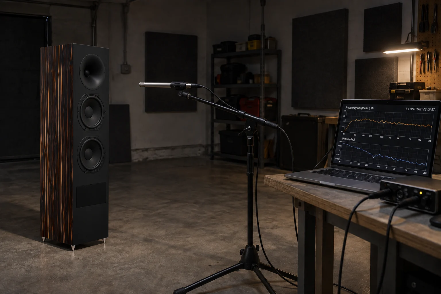
Calculations guide the work; measurements show how the assembled system behaves. During development we use a measurement microphone to examine frequency response and phase, then return to the crossover when the results call for a change.
A microphone position around one metre from the loudspeaker provides a useful reference for some of these checks. Its position and the measurement conditions must stay consistent when comparing changes. A metre is a setup choice, not a guarantee of a reflection-free measurement or a complete picture of the loudspeaker.
The room is present in the result too. Reflections and background noise need to be considered when interpreting a trace. Time-windowing can help separate the direct sound from later reflections, but a shorter window limits what can be resolved at low frequencies. Bass behaviour may require additional measurement methods.
Frequency response helps us see the balance across the spectrum. Phase behaviour helps us understand how the drivers combine through the crossover region. Listening then brings us back to the reason for doing this work: voices, instruments and music reproduced as a connected performance.
Built through a series of decisions
The finished surface is only the most visible part of the loudspeaker. Behind it are machined panels, a tuned internal passage, purpose-made parts and a crossover developed with the drivers it serves.
For us, building a loudspeaker means bringing those decisions together: cut, assemble, finish, measure and refine. Each stage gives the next one a better foundation.
Want to know more about the construction or finish options for a particular model? Talk to us about what you are considering.
Discuss your loudspeakers →